Motivation
I assembled my desktop way back when I started college which would be early 2019. Back then, I used an MSI B450M motherboard for my Ryzen 7 2700X plus an NZXT H510 for mATX compatibility and extensibility. Plus, it just looked good.

Fast forward to today, after a CPU RMA and two motherboard replacements, I have a Ryzen 5 5600X since it probably had better performance than the 2700X (it most likely had better performance-per-watt though). I got my latest motherboard due to it being on sale and I thought that it would solve some my USB issues (it did not). I still have the same case. I still love it as it provides me a lot of space to store my harddrives and SSD’s.
There is one problem that I have with it though. Aside from the white not looking as good due to my neglect, the power button seems to be failing. Usually, one click of the power button should turn the computer on but now I need to press it dozens of times in multiple orientations/position to get it to power on. Whevener I get fed up, I’d remove the glass front planel and short the power switch headers with a screwdriver to get the computer to power on.
Imagine my excitement when I discovered that my new motherboard support Wake on LAN?
Now, after a few months of dealing with it, I have decided to not deal with it anymore.
How I’ll deal with it
Now that I have attempted to give some believable excuse for why I spent so much time and money on this, let’s get into the specifics!
The Software
What’s Wake on LAN
Wake on LAN (WoL) is an Ethernet standard that allows you to remotely turn on a computer by using a “magic packet” that’s broadcasted to the entire subnet over UDP. This magic packet includes 6 bytes of FF and 16 repetitions of the Medium Access Control (MAC) or physical address of the computer’s Network Interface Controller (NIC). When looking at the bytestream, it would look like this assuming your MAC address is 00:11:22:33:44:55:
| |
Sending a Wake on LAN packet
We can verify what the magic packet will look like by using the wakeonlan Debian package:
Using a packet capture tool like Wireshark with a display filter set to ip.addr == 255.255.255.255, and after redacting the source MAC address and IP address, we can verify that this is what the magic packet looks like:

Receiving a Wake on LAN packet
Now that we know how to send a packet, we now need to setup the target system to handle a WoL packet. I’ll be using a Windows machine so I’ll follow directions for enabling WoL on a Windows machine. This typically includes:
- Enabling Wake on Magic Packet in the Ethernet adapter properties.
- Enabling Wake on pattern match in the Ethernet adapter properties.
- Setting WoL & Shutdown link speed to 10Mbps in the Ethernet adapter properties.
- Enabling Allow this device to wake the computer in the Ethernet adapater power management settings.
- Disabling Fast boot in Windows.
That should be enough for you to test on your own that a WoL packet will turn on your computer, if not, it is best to check if your motherboard or NIC support WoL in the first place.
ESP32 code
The following code is available on my Github and is a modified version of the Arduino OTA example sketch. That being said, the code has some features which are nice for a microcontroller that will be (mostly) in a sealed box like password-protected OTA support which enabled us to remotely upload sketches to the ESP32 without having to physically plug it in.
- By default, the code first connects to the defined SSID with the accompanying password.
- Then it sets the hostname and password to be used for the OTA service.
- After that it defines the OTA parameters to be used and some pin definitions.
- Lastly, in the loop, it checks for OTA connections then checks for a button press for the WoL packet.
| |
The Hardware
Parts list
- WEMOS LOLIN32 Lite (ESP32 with LiPo battery management)
- 3.7V “1000mAh” LiPo battery (with a JST plug)
- SPST toggle switch
- Kailh BOX Navy (probably the 1st version that killed GMK sets)
- White DSA keycap
- 2x 3mm LED’s
- 83mm x 58mm x 34mm project box
Schematic
 Here’s the schematic I made on a piece of cardboard that I also used to stop the drill from drilling my desk. The only reason I made this was to remember to solder the correct GPIO wire to the correct wires on the bridge. That being said, there are two main parts to this schematic, the switches and LED’s.
The first switch is the SPST toggle switch whose main job is to connect and disconnect the battery from the ESP32 to save on power. The second switch is a Kailh BOX Navy and its job is to generate the input for GPIO 23 in order to signal to the ESP32 to send the WoL packet. GPIO 23 was set to input mode and is active high, which is why it was set to input mode while using an internal pulldown resistor to avoid floating inputs.
The LED’s on the otherhand just need some current-limiting resistors to prevent them from blowing themselves up. One LED is connected directly between +3.3V and ground to signal that the device in turned on. The other LED is to signify that the device has connected to Wi-Fi successfully and is ready to send the WoL packet.
The ESP32’s GPIO pin count is not to scale.
Assembly


This was possibly the hardest part of this project, all the drilling. The hole for the SPST toggle switch was easy enough to make but the square Kailh BOX Navy switch was pretty hard to make. Who would’ve thought that making a square hole using a round drill bit would be hard?
Anyway, I did have some luck because the drill bit I was using was the same width as the LED’s I used, which was a nice surprise.


I think this was the point wherein it finally hit me that I didn’t have an actual plan for this. I had the initial components and what I wanted it to look like but no intermediate steps.
So I made this thing out of prototype boards that I soldered together to hold the two LED’s, their resistors, and some wires which help make everything more “structurally sound” and not just flying wires everywhere.


Here’s the “bridge” after soldering the current-limiting resistors.

Not my best soldering, but it’s good enough considering I still don’t have a jig setup to hold the thing that I’m soldering to.

“Repurposed” LED legs as wires to connect to the current-limiting resistors.
Left LED is for power, right is for the ready indicator.
The two leads from the resistors are both to be connected to ground.

Here is the ESP32 with a battery underneath it that’s double-sided taped to case.
I was also lazy and used cold splices for the SPST toggle switch and battery.

I then realized that I didn’t solder the power and GPIO batteries so I had to disassemble the ESP32 from the case and solder the wires to it, again without a holder.

Here is the entire bottom assembly which includes the battery and ESP32, now all that’s left is connecting the power and GPIO wires to the top half and the bridge from earlier.
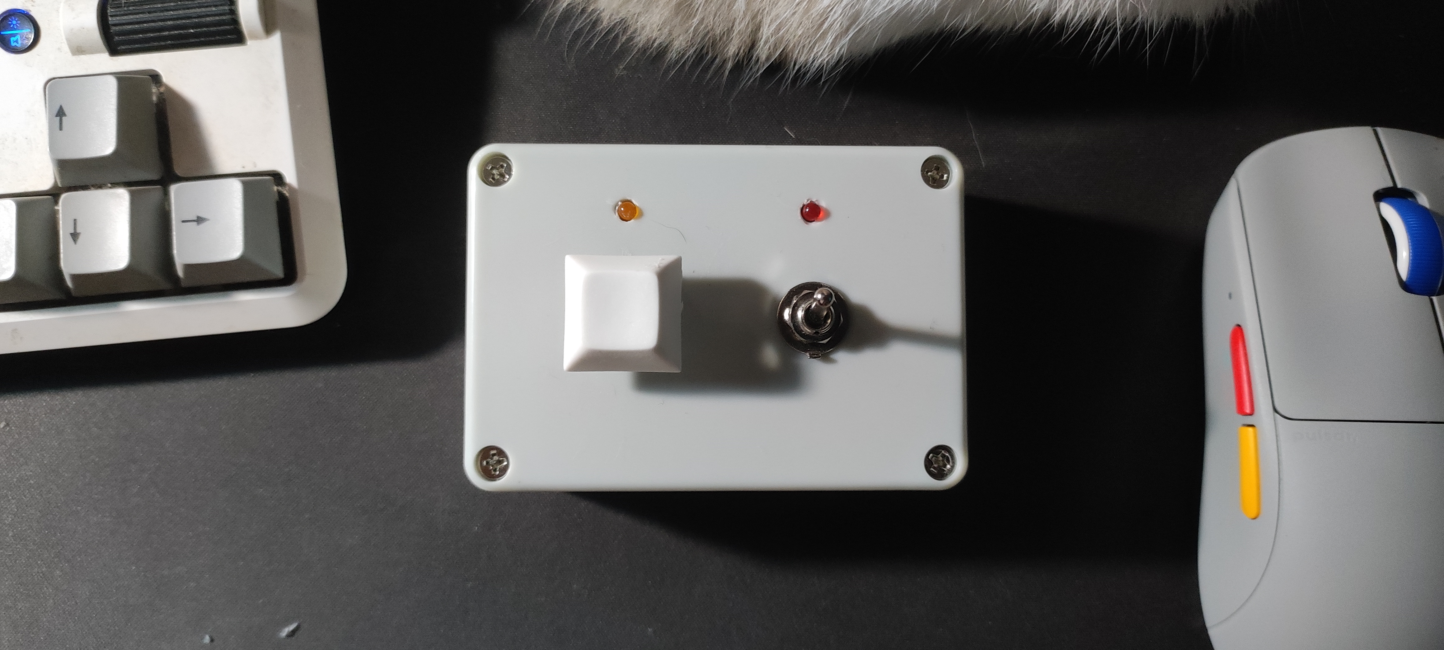
The finished thing


Here’s the fully-assembled thing. It works great but I definitely forgot to put a USB-C passthrough to be able to charge the battery without disassembling the whole thing. The orange LED also doesn’t seem to be happy with only 3.3V or is near death.
From fully off, it takes a few seconds usually to connect to the Wi-Fi network and be ready, but other than that, it works flawlessly.
Now I can turn my computer on without reaching below my desk and pressing the (possibly) broken button a dozen times.